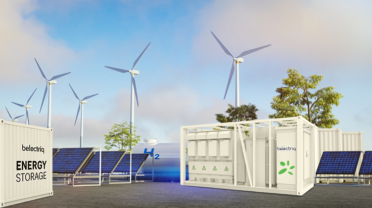
What is a Battery Energy Storage System?
In simple terms used in projects, a BESS is a battery‑based plant that soaks up excess electrical energy and puts it back when the system needs support. It is used in our kind of work for peak shaving, backup for sensitive loads, stabilizing frequency and voltage, and making solar or wind plants actually usable when demand does not match generation.
On the hardware side, a BESS is a combination of battery modules, the BMS, power electronics, protection, and a local controller. The design objective is straightforward: deliver the contracted power and energy for the agreed number of years, without safety incidents and with acceptable degradation.
Main pieces inside a BESS
Battery pack
Cell strings are built up to the DC voltage and MWh rating required for the site. Enclosures or containers take care of mechanical protection and environmental control.
Battery Management System (BMS)
The BMS keeps an eye on each module – voltage, temperature, current – balances cells, and enforces limits on State of Charge and operating window. If something goes outside the envelope, it alarms or trips.
Power Conversion System (PCS)
The PCS sits between the DC bus and the AC system. It is bidirectional, so it charges and discharges as per commands, follows grid codes for synchronization, and can provide reactive power.
DC / AC isolation
DC isolators, fuses and AC breakers allow safe maintenance and fault clearing. They separate the battery, PCS and upstream network when required.
Transformers
Step‑up or step‑down units match the PCS output to the site distribution level (LV to 11 kV / 33 kV etc.) and provide isolation where the scheme requires it.
Controls and communication
Local PLC / controller, SCADA links and EMS software define modes, setpoints and schedules and give the operator a clear view of alarms and trends.
How BESS differs from conventional backup
Diesel gensets and small UPS systems are essentially standby – they wait for an outage and then start. In a typical microgrid project, the battery energy storage system is used every day. It can charge when tariffs are low or when solar is spilling and discharge when the plant is close to its demand limit. Because the PCS responds in milliseconds, the BESS can also stabilize frequency and voltage in a way a slow‑starting generator cannot. In practice it is both a reliability asset and a commercial optimization tool, not just an emergency backup.
BESS in a Microgrid
Microgrid concept and where BESS sits
A microgrid is a local electrical system with its own generation, loads and controls, capable of running with the utility or in island mode. In the kind of sites you handle, this usually means some mix of PV, maybe wind or a small engine‑based plant, and a set of critical and non‑critical loads on a common bus.
The BESS is normally tied into the main AC bus through a PCS and transformer. The EMS coordinates the scheduling so that storage balances renewable swings, supports the bus during faults, and makes transitions between grid‑connected and islanded mode smooth from the user’s point of view.
Why the Single Line Diagram matters
The SLD is the basic document that shows how everything is wired: generators, BESS, transformers, feeders, breakers and protections. For BESS specifically it fixes the connection point and voltage, how fault currents are cleared, and how isolation is done for maintenance. A clean SLD catches issues like wrong voltage interfaces or missing breakers early in design instead of at site.
Typical microgrid with BESS – architecture
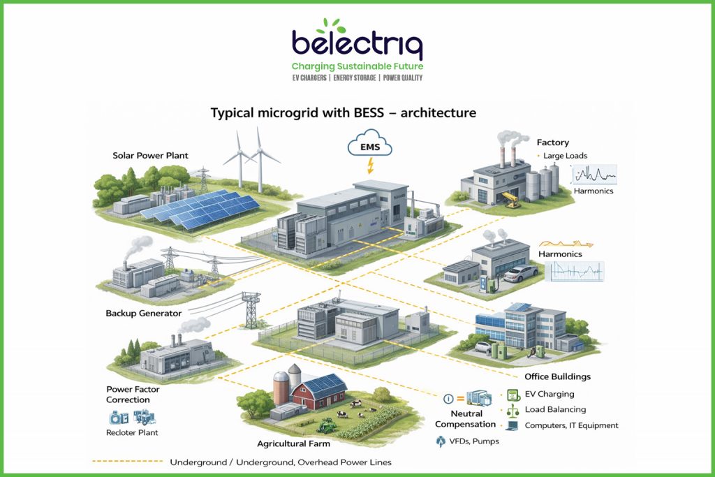
How the pieces line up
Generation
PV inverters connect to the MV bus through step‑up transformers. Any wind or small IC engines tie in at appropriate feeders, each through its own breaker and relay set.
Storage stage
The battery bank (hundreds of kWh up to multi‑MWh depending on the project) connects to a DC bus, which feeds a bidirectional PCS. A transformer links the PCS to the main AC bus if direct LV connection is not suitable.
Control and protection
BMS at pack level, EMS at plant level, and standard protection (overcurrent, voltage, frequency, anti‑islanding) tied into the overall protection philosophy.
Distribution
A main transformer and switchgear supply LV/MV feeders. Critical loads (process loads, data, medical, etc.) are kept on feeders that retain supply in island mode; non‑critical loads are placed on feeders that can be shed automatically or manually.
Grid interface
The point of common coupling (PCC) to the utility is via a breaker or static transfer switch. Control logic defines when to import, export, or island and under what conditions reconnection is allowed.
Day‑to‑day operation
How the BESS is actually used
Charging
- When PV / wind production is above the local demand and export is limited or not attractive, the EMS pushes that surplus into the batteries.
- At night or other off‑peak windows, charging from the grid can be scheduled when it makes commercial sense.
- Short opportunistic charging cycles are triggered if a clear solar window or a known peak later in the day is expected.
- Discharging
- During peak intervals, the BESS discharges to cap the site’s grid import and shave demand.
- For fast renewable fluctuations, it smooths the ramp so the grid or local generators see a gentler profile.
- In island mode it often becomes the main frequency and voltage reference.
- After a total outage, the BESS can energize the bus and allow a controlled black start sequence.
- Standby
When there is no clear benefit in either direction, the storage is usually held around a mid‑SOC band, which is kinder to battery life and still leaves room for both up and down regulation.
Electrical requirements
Voltage and frequency points to note
On the DC side, most current designs sit in roughly the 400–800 V window for the battery strings, chosen to match the PCS design and safety rules. On the AC side, small systems connect at 400 V; larger schemes go through transformers to 11 kV, 22 kV or 33 kV, and very large plants connect at higher transmission levels.
In grid‑connected mode the inverter tracks the utility frequency (50 or 60 Hz depending on country) and must stay within the tolerances defined by the local code. In a stand‑alone microgrid, the BESS often sets the frequency and other sources follow. Voltage at the main bus is kept within the allowed band (typically around ±10% of nominal) by a mix of active and reactive power control.
Why use BESS in microgrids
Benefits in practice
- Better utilization of PV / wind by avoiding curtailment and shifting energy into the evening.
- Lower demand charges and deferred network capex by clipping peaks instead of uprating transformers and feeders.
- Higher reliability for priority loads, shorter recovery after grid faults, and the option to island during poor grid conditions.
- Ancillary services at local level: frequency support, fast reserve‑type behavior, voltage regulation, and some congestion relief.
- Reduced diesel consumption and emissions where generators are still used.
Typical sites
Industrial estates, ports, and process plants use BESS‑based microgrids where even a brief interruption is costly. Hospitals and water utilities use them to protect essential services. Remote villages, islands and mines pair local renewables with storage to cut diesel dependence. Campuses and smart‑city pilots use such systems as living labs that also host EV charging, demand response, and other pilots.
Design and protection points
Sizing the storage
The sizing exercise revolves around: peak and average demand, required backup hours for critical feeders, behavior of local renewables, cycling expectations, and acceptable round‑trip losses. For example, a 2 MW critical load needing four hours of autonomy starts at 8 MWh on paper, but once you respect SOC limits and losses, the installed capacity has to be higher. More mature projects use simple optimization tools that take tariffs, degradation and forecast errors into account.
Protection and safety
Electrical protection covers overcurrent on DC and AC, over/under‑voltage, frequency trips and the anti‑islanding requirements at the PCC. Thermal protection relies on temperature sensors, suitable cooling design and proper fire detection / suppression inside containers or rooms. On top of that, communication links between the battery system, EMS and external control rooms are hardened and access‑controlled to reduce cyber risk.
Looking ahead
Developments to watch
Vendors are working on higher‑density and safer chemistries (including solid‑state), hybrid storage that mixes batteries with supercapacitors or flywheels, and practical vehicle‑to‑grid schemes where EV fleets act as a flexible resource. Second‑life EV packs are already being trailed in stationary projects where reduced capacity is acceptable. Modular container solutions are now common, allowing sites to start small and add more “blocks” of storage as load and renewable capacity grow.
Leave a Reply